Abstract — This article analyzes the application of the negative-sequence overcurrent element in the protection of
electrical systems, comparing its performance with the traditional phase and zero-sequence elements.
Although often overlooked in practice, the negative-sequence element offers advantages when analyzed in modern
microprocessor-based relays. The study used a 16-bus test system, modeled in
PowerFactory 2024 software with real data from the Furnas system, considering voltages of 138 kV, 230 kV and 345 kV. More than
300 Phase-Phase, Phase-Phase-Ground and Phase-Ground faults were simulated, evaluating the operating time and
reach of the different protection elements. The results indicate that the negative-sequence element
had greater reach in 100% of Phase-Phase faults and operated faster in up to 90% of these
events. It also proved effective in scenarios where the traditional elements would not operate, due to
fault currents lower than load currents. The systematic inclusion of the negative-sequence element can
significantly improve selectivity, reduce interruption time and minimize damage to faulted equipment.
Keywords — Protection Systems, Overcurrent Protection, Symmetrical Components, Coordination,
Selectivity, Negative-Sequence Protection Functions.
-
- INTRODUCTION
The design of protection systems for the electric power system (EPS) is based on fundamental principles
such as simplicity, reliability, selectivity, ease of maintenance and fast operation. These
requirements aim to reduce permanent damage to system assets, preserve people’s safety, minimize
interruption times and isolate the smallest possible portion of the system affected by a fault [1], [2].
During abnormal conditions, such as faults and unbalances, negative-sequence components appear in the electrical
quantities of the EPS. These components reflect the asymmetry between phases and indicate the presence of operating
anomalies. Modern protection relays, especially microprocessor-based ones, allow these
components to be used in protection algorithms, offering highly sensitive and reliable functions [8].
Historically, the use of negative-sequence functions was limited by the complexity and high cost of the
techniques required in electromechanical and solid-state relay technologies. Despite being technically feasible,
processing these quantities was not trivial, which discouraged their practical application. With the evolution of
microprocessor-based relays, accessing and using negative-sequence components has become
significantly simpler. Even so, these functions remain underused in engineering
practice and are often passed over in favor of conventional phase and zero-sequence elements.
Knowing how the elements of an electrical system behave, under both normal and
fault conditions, is essential for the proper application of protection functions. The authors recognize that the
protection system has several functions, each with specific roles in detecting and clearing faults.
In this context, the overcurrent function is generally used as backup protection. Accordingly, this
work aims to analyze the performance of traditional overcurrent protection elements and
compare it with protection based on the negative-sequence element for different types of faults in
transmission systems.
To this end, the reach and operating times of the phase, negative-sequence and zero-sequence elements are evaluated
through simulations on a test system modeled on real data from the Furnas System in the
Goiás/Brasília region, considering three voltage levels: 138 kV, 230 kV and 345 kV [6]. The results show that
negative-sequence protection can offer significant advantages in terms of speed and coverage, reinforcing its relevance in practical EPS protection schemes based on overcurrent functions.
- INTRODUCTION
-
- CRITERIA FOR SETTING OVERCURRENT PROTECTION
When setting the phase time-overcurrent element, the relay must withstand, without operating, routine
load variations in the system (40% to 50% margin). In addition to accommodating load current fluctuations, this margin
allows for load transfers due to network switching and future expansions [1].
For the case studied here, an overload factor of 50% was applied, as given in (1).
- CRITERIA FOR SETTING OVERCURRENT PROTECTION

Where:
In — Rated load current;
Iaj — Protection relay pickup current;
Icc. min. — Minimum short-circuit current.
When setting the zero-sequence overcurrent element, the neutral relay setting depends on the location and
size of the electrical system. In the generation zone, current is more balanced. In distribution,
unbalance is greater, as shown in Figure 1 [1].
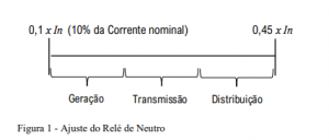
For the case studied here, transmission line protection, a 20% unbalance factor was applied, as given in (2).

Where:
In — Rated load current;
Iaj — Protection relay pickup current;
Icc. min. 0 — Minimum zero-sequence short-circuit current.
Like zero-sequence overcurrent elements, negative-sequence overcurrent
elements can be set below load current levels [1].
Compared with traditional phase overcurrent protection, the negative-sequence overcurrent element can be set to operate faster and with greater sensitivity for Phase-Phase faults, since it does not respond to balanced load conditions [3].
Table 1 below shows which elements, phase or zero-sequence, are commonly used to detect the various types of faults that occur in the EPS.
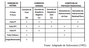
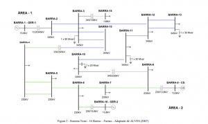
Table 1 shows that phase overcurrent elements are used to detect faults involving two or more phases, while residual (or ground) overcurrent elements are applied to faults involving ground. This protection structure reflects a conventional approach based on the direct use of phase currents (Ip) and zero-sequence current (I0) as primary operating quantities. However, this approach does not comprehensively consider the use of negative-sequence components (I2), despite their consistent presence in asymmetrical operating conditions, such as single-phase-to-ground (PG), phase-phase-to-ground (PPG) and phase-phase (PP) faults. Microprocessor-based relays allow real-time processing of symmetrical components, enabling the implementation of I2-based protection functions. Such functions offer high sensitivity to asymmetry and can be used as discriminating elements in detecting unbalanced faults, including situations where conventional phase or ground elements have limitations in sensitivity, selectivity or coordination. In this sense, using negative-sequence current as an operating quantity is an effective strategy for detecting PG, PPG and PP faults. In PG and PPG faults, I2 appears together with I0 and can act as a redundant or complementary element to the zero-sequence element. For PP faults, where no I0 is generated, the use of I2 becomes even more relevant, offering a robust alternative in scenarios where operation based solely on Ip may be compromised by low fault current levels or the presence of unbalanced loads. Therefore, adopting negative-sequence protection elements, made possible by microprocessor-based relays, is a natural and technically justifiable extension of conventional protection, contributing to greater sensitivity, selectivity and speed of response in electric power systems. 3. METHODOLOGY The test system for this work is the 16-bus system, heavy-load base case, derived from data from the Furnas system – Goiás/Brasília region, at three voltage levels: 138 kV, 230 kV and 345 kV [6]. PowerFactory (PF) 2024 software was used to model and analyze the electrical system. The test system was supplemented with technical data on line lengths and with the insertion of protection and measurement equipment — current/potential transformers and protection relays — enabling analysis of the protection elements’ operation. The system has two electrical areas: area 1, which concentrates the 345 kV sector, and area 2, at 230 kV. It has two generating plants, one of 422 MW (maximum generation) in area 1 and another of 420 MW (3 x 140 MW – maximum generation) in area 2. The meshed transmission network, with single and double circuits, totals fourteen circuits. It has three interconnection transformers between different voltage levels for voltage control, a synchronous condenser connected to bus 9 and shunt devices: three reactors and one capacitor. It is still a somewhat didactic system, but it has the characteristics of a real system, as shown in Figure 2:
The simulations aim to evaluate the applicability and reach and compare the operating times of the overcurrent protection elements under the following conditions: Phase-Phase faults – comparison of phase and negative-sequence element operation; Phase-Phase-Ground faults – comparison of phase and negative-sequence element operation and of negative-sequence and zero-sequence element operation; Phase-Ground faults – comparison of zero-sequence and negative-sequence element operation. As shown in Table 1, current electrical studies propose the following protection coverage: Three-phase faults, Phase-Phase faults and Phase-Phase-Ground faults: use of phase overcurrent elements; Faults involving ground, Phase-Phase-Ground and Phase-Ground: use of zero-sequence overcurrent elements. In the technical literature, the negative-sequence element is applied only to a limited extent in defining protection schemes. This element can be set similarly to the zero-sequence element and, compared with the phase overcurrent element, has the advantage of operating faster under unbalanced conditions, since it does not respond to balanced loads. This study therefore proposes using the negative-sequence element to detect PG, PPG and PP faults, replacing the traditional phase and zero-sequence overcurrent elements. The expectation is to increase both the sensitivity and the speed of response of the protection. The phase and zero-sequence element settings followed the guidance of the traditional literature [1], [2]. In this study, the negative-sequence element was set analogously to the zero-sequence element, considering 20% unbalance, as given in (3):

Where: — Rated load current; — Protection relay pickup current; — Minimum negative-sequence short-circuit current. 4. RESULTS The analysis involved simulating more than 300 faults — bolted Phase-Phase, Phase-Phase-Ground and Phase-Ground faults — at the various buses and along the system lines, with the results detailed below. In the test system – Area 1 of Figure 3, 345 kV sector, a Phase-Phase short circuit was applied at bus 10, and the operating time and reach of the relays involved were evaluated, according to the schematic circuit shown in Figure 3.
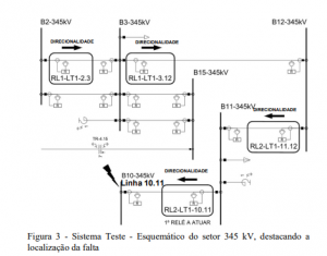
The coordination chart in Figure 4 highlights, for the same relay, the operating time of the phase element (425 ms) and the faster operation of the negative-sequence element (398 ms) for the same fault. Analyzing the operation of the other relays for this fault at Bus 10, the times and operating differences were recorded as shown in Table 2. RL2-LT1.10.11, closest to the fault, operates first, and the others act as backup.
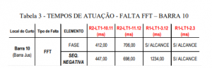
The results in Table 2 indicate that the negative-sequence element operated faster in the first two relays; moreover, this element provided reach to all the relays involved. The protection philosophy must ensure there is no loss of selectivity, even with the long reach associated with the negative-sequence element. Extending the analysis of Phase-Phase faults along line 10.11, at intervals of 12.5% of the transmission line length, the following relay operating times are obtained, as in the example of relay RL2-LT1.11.12 shown in Figure 5 below. The results refer only to cases in which the relay operates for both elements: phase and negative sequence.
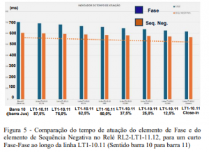
Figure 5 shows that the negative-sequence element operates faster than the phase element along 100% of the line length. If all relays picked up by the Phase-Phase fault at Bus 10 are included in this analysis, the operating times fall within the limits shown in Figure 6.
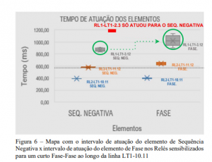
Figure 6 shows that the operating limits of the negative-sequence elements are lower than those of the phase elements for all relays compared. In relay RL2-LT1-11.12, for example, all negative-sequence operations were below 600 ms, while the phase element starts at 620 ms. It is important to note that, for this fault, only the negative-sequence element reached relay RL1-LT1-2.3. The phase element did not operate. Similarly, the following faults were applied: – Phase-Phase-Ground, comparing phase x negative-sequence elements and negative-sequence x zero-sequence elements; – Phase-Ground, comparing negative-sequence x zero-sequence elements.
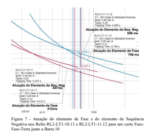
In the coordination chart in Figure 7, in addition to comparing operating times, the coordination interval can be seen to range from 251 to 294 ms. Including all relays picked up for this PPG fault at Bus 10, Table 3 shows the following operating times:
Table 3 shows that the difference in operation between the elements is below 35 ms and that, in this case, as with the Phase-Phase fault, the phase element picks up in fewer relays, limiting backup protection. Applying the other proposed faults at both voltage levels (345/230 kV) and in both directions, and considering only cases in which both elements evaluated operated for the same fault, Figure 8 shows which element operated faster for faults involving more than one phase.
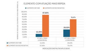
Analysis of the results showed that the negative-sequence element had shorter operating times in 87.65% of Phase-Phase fault cases and in 70.47% of Phase-Phase-Ground fault cases, as shown in the comparison chart. Likewise, Figure 9 shows which element operated faster for faults involving ground.
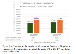
For PPG faults, the negative-sequence element was faster in 56.72% of cases, versus 43.27% for the zero-sequence element. For PG faults, the negative-sequence element also performed better, with 54.39% of faster operations versus 45.61% for the zero-sequence element. After analyzing operating times, with a focus on evaluating the reach of the protection elements, 146 cases were identified — among all simulated faults and the four relays evaluated, considering directionality — in which at least one protection element was not picked up with the settings applied.
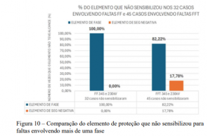
Analysis of the results indicated that, in the 32 Phase-Phase fault cases in which at least one protection element was not picked up, the phase element accounted for 100% of occurrences. In the 45 Phase-Phase-Ground fault cases, the phase element was also not picked up in 82.22% of occurrences, as illustrated in the chart. Likewise, Figure 11 shows the percentage of non-operation of protection elements specifically for faults involving ground.
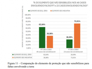
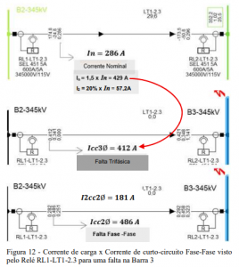
The results show that, in the 46 PPG fault cases in which at least one protection element was not picked up, the zero-sequence element accounted for 63.04% of occurrences. In the 23 PG fault cases, the zero-sequence element was also not picked up in 26.09% of occurrences, as illustrated in the chart. In this study, more than 300 faults were simulated — Phase-Phase, Phase-Phase-Ground and Phase-Ground — at the various buses and along the system lines, with the following main results: For Phase-Phase faults, in 100% of cases the negative-sequence element had greater reach than the phase element; For Phase-Phase faults, in about 90% of occurrences the negative-sequence element operated 25 to 75 ms faster than the phase element; For Phase-Phase-Ground faults, in 75% of cases the negative-sequence element operated faster than the phase element, by 90 ms on average; For Phase-Ground faults, in 54% of cases the negative-sequence element was more effective than the zero-sequence element. This is mainly because, on some system lines, I0 is greater than the phase-to-ground short-circuit currents, preventing the zero-sequence element from being set, as illustrated in Figure 13. At some points in the system, the pickup current (a function of rated current) of the phase element Ip is higher than the fault currents, as shown in Figure 12, restricting the application of this element. Since the negative-sequence element is set by the unbalance current I2, a percentage of load current, there is no such restriction.
In other regions of the system, the pickup current of the zero-sequence element, set by current I0 (a percentage of load current), is higher than the ground fault currents, as shown in Figure 13, preventing the application of the zero-sequence element and allowing only the negative-sequence element.
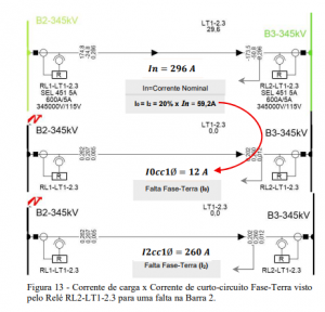
Figure 13 shows the zero-sequence current (I0 = 59.2 A) higher than the phase-to-ground fault current (I0cc1Ø), preventing the application of the zero-sequence element according to the requirements set out in (2). The results reinforce the importance of analyzing the application of the negative-sequence element as a protection function in electrical systems. Based on the results, the application of the negative-sequence element is proposed as shown in Table 4 below.

5. CONCLUSIONS This article addressed the application of the negative-sequence element as a protection technique in electrical systems, an approach still little explored in the existing literature. By implementing a real test system, it was possible to compare the performance of the negative-sequence element with the phase and zero-sequence elements, focusing on operating time and reach. The results indicated that the negative-sequence element performed better, with faster operating times and greater reach than the traditional phase and zero-sequence elements. Regarding reach, it is important to highlight both the benefits and the limitations of this characteristic. On the positive side, greater reach makes it possible to cover all relays along the circuit, increasing protection sensitivity and ensuring broader fault detection. In addition, this reach can be adjusted (shortened), allowing some flexibility in system configuration. On the other hand, this same extended reach can be a disadvantage, as it may increase the risk of loss of selectivity between protection devices. The application of the negative-sequence element must therefore be carefully evaluated by the responsible engineer, considering the protection philosophy adopted and the specific requirements of the installation. The initial proposal was to use the negative-sequence overcurrent element to detect phase-ground (PG), phase-phase-ground (PPG) and phase-phase (PP) faults, fully replacing the conventional phase and zero-sequence overcurrent elements. Based on the results obtained, it is proposed that the protection philosophy consider the operating quantities as indicated in Table 4. These results have significant implications for improving the reliability and efficiency of protection systems, especially in regions where phase or zero-sequence elements are not effective due to specific rated and fault current characteristics. The faster operation of the negative-sequence element helps reduce interruption time, minimizing damage to equipment within the protection zone and, consequently, ensuring greater operational safety. Although the study was carried out with a real test system, some limitations must be considered, such as dependence on the specific operating conditions of the system studied. This analysis is being extended to applications in industrial systems, with the aim of verifying whether the gains in sensitivity and speed of response observed in electric power systems are also reproduced in that context.
Nilson Cunha Júnior Electrical, Instrumentation & Automation Manager A1 ENGENHARIA Araucária, PR 83707-090 – Brazil Tel.: + 55 (41) 3616-3616; email:[email protected] Prof. Dr. Ulisses Chemin Neto Professor PPGSE Federal University of Technology – Paraná – UTFPR Curitiba, PR 80230-901 – Brazil Tel.: + 55 (41) 3310-4626; email: [email protected] Dr. Fabiano Magrin Engineer FGSM Engenharia Campinas, SP 13025-340 – Brazil Tel.: + 55 (19) 981142808; email: [email protected]