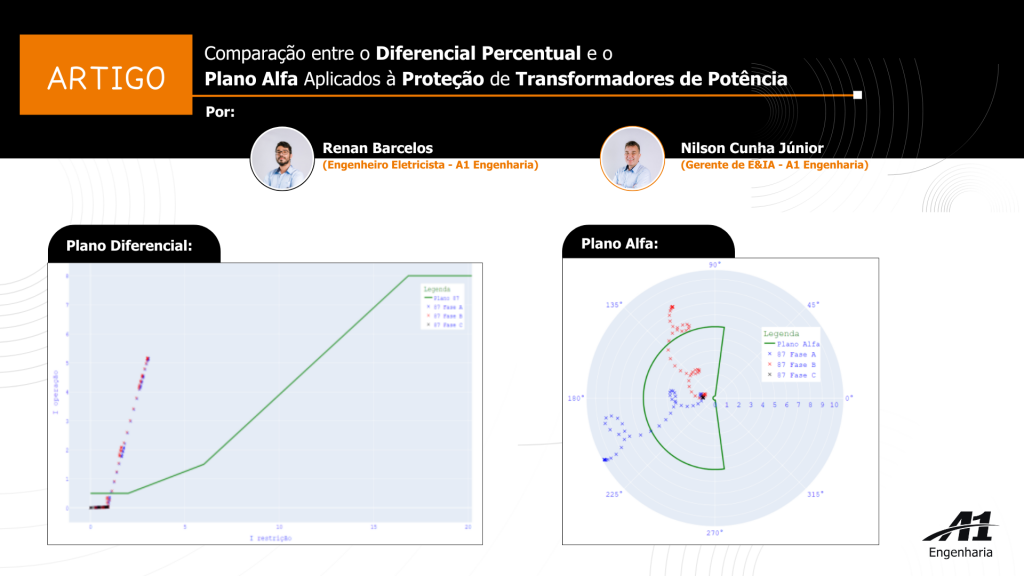
Abstract: The alpha plane consists of a geometric representation of the ratio of the currents entering and leaving a protection zone in a complex plane. The relay manufacturer Schweitzer Engineering Laboratories uses this plan in its line differential relays, but not for application in power transformers. Therefore, this paper presents a comparison between the alpha plane and the percentage differential applied to the protection of power transformers. The alpha plane was implemented in a SEL-451 protection relay through programming in the relay’s proprietary language. The use of the differential element through the alpha plane resulted in a significant reduction in the protection actuation time. With this reduction in the operating time, it is expected to significantly decrease the electrical and mechanical damage caused to the transformer during faults, considering the reduction in the time the equipment is exposed to faults.
Abstract: The alpha plane is a geometric representation, in a complex plane, of the ratio between the currents entering and leaving a protection zone. The relay manufacturer Schweitzer Engineering Laboratories uses this plane in its line differential relays, but not for power transformer applications. This article therefore compares the alpha plane with the percentage differential applied to power transformer protection. The alpha plane was implemented in a SEL-451 protection relay through programming in the relay’s own language. Using the differential element through the alpha plane resulted in a significant reduction in protection operating time. With this shorter operating time, the electrical damage and mechanical stress on the faulted transformer are expected to decrease considerably, given the reduced time the equipment is exposed to faults.
Keywords: Alpha plane, percentage differential, protection, power transformers.
Keywords: Alpha plane, protection, percentage differential, power transformers.
1. INTRODUCTION
In Brazil, demand for electricity is increasing, which requires a guaranteed high-quality supply (EPE, 2022). Because of the size of the country, many power plants are far from consumption centers, making it necessary to use transformers to step up the voltage and reduce losses during transmission. Transformers convert electrical energy to different voltage levels, enabling efficient transmission. They consist of coils wound on a ferromagnetic core and play a vital role in electrical systems.
Although power transformers generally have low failure rates compared with other electrical system equipment, when these failures occur unexpectedly they lead to the tripping of certain transmission lines, overloads on other transformers, the need for replacement and/or maintenance, the shutdown of various sectors in the affected area, switching operations to work around the contingency and the possibility of a long delay in returning the faulty equipment to service. Failures in power transformers are therefore harmful, costly and dangerous for both utilities and consumers. It is thus important to protect these transformers properly. There are several protection methods, depending on the transformer’s rating. Fuses can be used for smaller transformers, while current differential, instantaneous and time overcurrent protection, among others, are commonly used for larger ones. The choice of protection method should be based on careful analysis by the protection engineer, considering technical and economic feasibility and the importance of the transformer.
For transformer protection, there is the IEEE Guide for Protecting Power Transformers, C37.91 (IEEE STD. C37.91-2021, 2021), which presents several possible types of protection. However, as its name suggests, C37.91 is a guide to solutions and is not intended to compare them; it is therefore up to the protection engineer to carry out a tailored analysis for each application, according to the importance of the transformer to be protected.
This article compares the percentage differential and the alpha plane. To do so, turn-to-turn and turn-to-ground faults are simulated under full-load and no-load conditions on the delta and wye sides of the transformer. The main objective of this work is to compare the two methods and verify their behavior for these faults. Protection performance using the alpha plane was superior to the percentage differential.
2. THEORETICAL BACKGROUND
To better present the subject of this article, this chapter provides theoretical background on transformers, on how percentage differential protection works and on how the alpha plane works.
2.1 Transformer
The transformer is an extremely important piece of equipment for the operation of the electrical system as we know it today. As described above, most power plants are located at a great distance from consumption centers. Step-up transformers are therefore needed to enable transmission and, closer to these consumption centers, step-down transformers are used to reach voltage levels at which electricity can be distributed in a technically and economically viable way.
The transformer enables electricity transmission through the principle of electromagnetic induction, converting electrical energy at a given frequency and voltage level into electrical energy at the same frequency, changing only the voltage level, which is proportional to the number of turns in the windings, the magnitude of the mutual flux and the frequency (CHAPMAN, 2013; FITZGERALD et al, 2014).
Compared with other electrical system equipment, the transformer is one of the simplest and may consist of two or more coils of conductors wound around a ferromagnetic core. Except for autotransformers, these coils have no physical connection to one another; the mutual magnetic flux within the core is the only connection between them (CHAPMAN, 2013).
2.2 Transformer protection
Power transformers are susceptible to several types of faults, such as (PAITHANKAR, Y.G. & BHIDE, S.R., 2003; RUSH, P., 2011):
· Phase-to-ground and phase-to-phase faults at their terminals;
· Turn-to-ground and turn-to-turn faults in their windings;
· Faults caused by breakdown of the insulating oil;
· Faults in the on-load tap changer;
· Sustained or uncleared external faults.
The IEEE Guide for Protecting Power Transformers, C37.91 (IEEE STD. C37.91-2021, 2021), defines four categories of power transformers, as shown below:
· Category I: single-phase from 5 to 500 kVA and three-phase from 15 to 500 kVA;
· Category II: single-phase from 501 to 1667 kVA and three-phase from 501 to 5000 kVA;
· Category III: single-phase from 1668 to 10000 kVA and three-phase from 5001 to 30000 kVA;
· Category IV: single-phase ≥ 10 MVA and three-phase ≥ 30 MVA.
Also according to C37.91, there are several methods for protecting transformers, depending on their rated power. For example, for small three-phase transformers up to 5 MVA (categories I and II), protection can be provided by fuses. For three-phase transformers rated above 5 MVA (categories III and IV), the most widely used protection is current percentage differential (87T). This allows fast fault detection, which can reduce the damage caused by fault current, and also distinguishes internal faults from other operating conditions. Instantaneous overcurrent (50) and time overcurrent (51) protection are generally used together with current differential protection as backup protection. For large transformers, restricted earth fault protection (REF – Restricted Earth Fault
protection) is also used, together with so-called intrinsic protections such as pressure relays, oil level relays, gas detector relays (Buchholz relay) and winding overtemperature thermal relays (49), among others.
As noted by Magrin (MAGRIN, 2017) in his doctoral thesis, percentage differential protection is the most widely used for transformer differential relays, since it offers high speed and reasonable sensitivity for detecting and clearing transformer faults.
2.3 How percentage differential protection works
Differential protection works by comparing input and output current: during normal operation, the sum of the currents entering the protection zone equals the sum of the currents leaving it. In other words, differential protection operates based on Kirchhoff’s Current Law (KCL). The protection zone of the differential function is delimited by the current transformers (CTs), which measure the currents in their primary windings and send these currents, scaled by the CT’s rated ratio (CTR), to the protection relay (BLACKBURN, J.L., & DOMIN, T.J, 2014). On receiving these current values, the relay decides, according to its programming logic, whether to restrain or operate — that is, whether or not to send the trip signal to the circuit breakers within its protection zone.
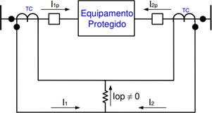
The operating principle of differential protection is illustrated in Figure 1, operating under normal conditions. To simplify the explanation, only two circuits are shown; there may be several circuits, but the principle is the same, with the CTs as the limits of the protection zone. During normal operation, the sum of the incoming currents is basically equal to the sum of the outgoing currents. The currents are represented in per unit (pu), since the currents do not have the same magnitude on either side of the transformer.
Fig. 1 Differential protection operating scheme.

Source: Taken from Magrin (2017).
I1p and I2p are the primary currents entering and leaving the protection zone. Iop is the difference between the currents entering and leaving the transformer, which under normal conditions is given by the transformer’s excitation current.
During normal operation or during external faults, the difference between the currents entering and leaving the protection zone is given by the transformer’s excitation current. This current is called the operating current and can be expressed as the phasor sum in equation (1):

Where Î1 is the current in the primary CT and Î2 is the current in the secondary CT.
With the system operating under load or during an external fault, the operating current should be negligible; only a small portion is due to internal losses, and magnetizing currents cause an imbalance. In general, these currents are less than 3% of the transformer’s rated current. Differential relays are very sensitive to internal faults when the currents in the restraint windings flow in opposite directions or when one of the restraint currents is zero (BLACKBURN, J.L., & DOMIN, T.J, 2014; MAGRIN, 2017; SEL, 2019).
When internal faults occur, Figure 2 shows that the operating current of the differential relay is essentially the sum of the input currents feeding the fault, I1p and I2p. This is the total secondary fault current and, since these currents have the same angle, they flow through the relay’s operating coil.
Fig. 2 Differential protection operating scheme.
Source: Taken from Magrin (2017).
Because of transformer characteristics that cause false differential currents, such as ratio errors and tap variation, most differential relays are of the percentage differential type, in order to provide high sensitivity to light internal faults with high security, i.e. high restraint for external faults.
- How the alpha plane works
The alpha plane was introduced by Warrington in 1968 (WARRINGTON, 1968), who presented the alpha and beta complex planes to evaluate the longitudinal differential protection of pilot relays.
Through the alpha plane, Warrington (1968) sought to better represent the relationship between the phasor currents of the differential element. This representation is given in a complex plane, based on the following equation.

where alpha α is the ratio between the current at the remote terminal ÎA and the current at the local terminal ÎB.
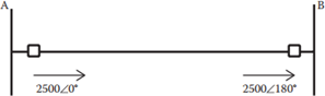
In Blackburn and Domin (BLACKBURN, J.L., & DOMIN, T.J, 2014), the alpha plane is first presented as a current-ratio differential concept, in which relays used in transmission line differential protection continuously calculate the ratio between the phasor currents of the remote and local terminals. When plotted on a complex plane, this ratio makes it easier to understand the characteristics and performance of the differential element used. Consider a transmission line operating under normal conditions, as shown in Figure 3.
Fig. 3 Example of a TL operating under normal conditions.
Source: Adapted from Blackburn & Domin (2014).
Applying equation 2 to obtain α, as presented by
Warrington (1968), gives the following result:

This operation yields the point at which the alpha plane represents fully normal operating conditions, and this point remains constant regardless of the magnitude of the current flowing through the line. Since the line is within the protection zone, external faults with no CT errors would also be plotted at point -1. If there are CT errors, whether due to phase shift, saturation or other causes, the plotted point would change in angle and magnitude, but it would remain on the left side of the alpha plane.
For faults inside the protection zone, current flows from the buses toward the fault point; checking with equation 2, the plotted point will be 1, meaning the fault will be on the right side of the alpha plane.
In practice, due to system characteristics, the currents flowing to the fault point are not equal, but the plotted point will still be on the right side of the plane.
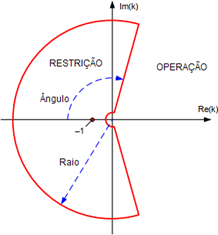
The restraint area is defined by the radius and angular extent of the circle in the plane. These are configurable in the protection relay. With the radius and angle properly set, the alpha plane looks as shown in Figure 4.
Fig. 4 Alpha plane characteristic.
Source: Adapted from SEL (2014a).
For internal faults fed from only one side of the protection zone, the current ratio will be zero. To ensure proper operation in this case, the inner radius of the circle in the SEL-311L relay is equal to the inverse of the outer radius (SEL, 2021a).
- METHODOLOGY
The power system used for this article was taken from the doctoral thesis of Professor Dr. Fabiano Magrin (MAGRIN, 2017). It is a simple system with just one source, the transformer bank and the load. This system was used to analyze whether or not the differential relay operates according to the behavior of the transformer’s currents and voltages during internal and external faults.
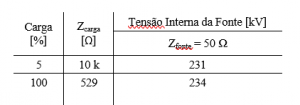
Table 1 presents the data for operation from no load to full load, the source impedance values and the voltages needed to keep the system operating at 1 pu at bus S in the pre-fault condition. Figure 5 shows the power system developed by Professor Fabiano Magrin for his thesis. For this article, this system was used to analyze the behavior of the transformer’s electrical quantities under fault. The power system studied in this article was developed in an institutional version of the PS Simul program, provided free of charge by CONPROVE Engenharia to UTFPR.
Table 1 – Power system data.
Source: Adapted from Magrin (2017). Fig. 5 Test power system.
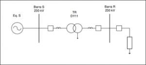
Source: Adapted from Magrin (2017).
The system used three single-phase transformers of 33.33 MVA each, totaling 100 MVA, with 10% leakage reactance and 0.1% resistance, the percentage values being on the transformer base. To make it easier to compare voltages and currents on both sides, a 1:1 transformation ratio was chosen.
The aim was to evaluate fault detection at the critical points of the windings where, according to Magrin (2017),
the winding locations with the lowest sensitivity for differential fault detection are the following:
- 1% to 10% on the wye side for turn-to-turn and turn-to-ground faults;
- 1% to 10% on the delta side for turn-to-turn faults;
- 45% to 55% on the delta side for turn-to-ground faults.
For this article, several types of faults were simulated in the power system:
- Bolted turn-to-turn and turn-to-ground faults in the delta winding under full-load and no-load conditions;
- Bolted turn-to-turn and turn-to-ground faults in the wye winding under full-load and no-load conditions.
- COMPARISON BETWEEN THE ALPHA PLANE AND THE PERCENTAGE DIFFERENTIAL
This chapter compares the behavior of both planes and their operating times: the native percentage differential of the SEL-387 relay and the alpha plane implemented through internal logic in the SEL-451 relay.
Figure 6 shows the behavior of a turn-to-turn fault in the percentage differential plane, where the phase A and B currents leave the restraint region and enter the operating region, causing the relay to issue the trip signal. Figure 7 shows the behavior of the currents for a turn-to-turn fault in the alpha plane. Both differential elements under study operated. Note that, due to the transformer’s connection type, a single-phase fault involving phase A picks up the phase A and B elements without operating the phase C element. This is because, in a delta-wye transformer, a single-phase fault on the wye side is seen from the delta side as a two-phase fault.
Fig. 6 Behavior of the currents in the percentage plane.
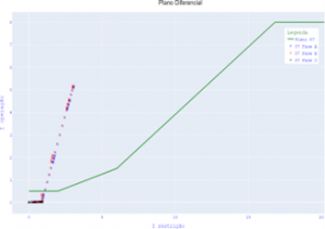
Source: The authors (2023).
Fig. 7 Behavior of the currents in the alpha plane.
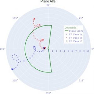
Source: The authors (2023).
- Turn-to-turn faults
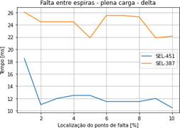
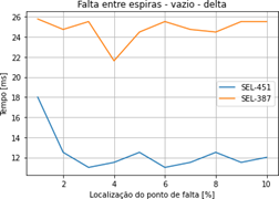
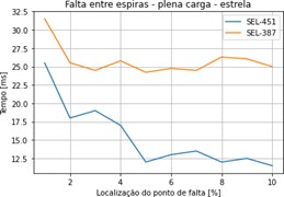
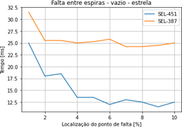
For turn-to-turn faults, both differential planes operated in all simulations, i.e. there was no difference in sensitivity, but using the alpha plane significantly reduced the operating time. Figures 8, 9, 10 and 11 show the difference in operating times of the SEL-451 and SEL-387 relays for the same turn-to-turn fault simulations.
Fig. 8 Turn-to-turn fault in the delta winding at full load.
Source: The authors (2023).
Fig. 9 Turn-to-turn fault in the delta winding at no load.
Source: The authors (2023).
Fig. 10 Turn-to-turn fault in the wye winding at full load.
Source: The authors (2023).
Fig. 11 Turn-to-turn fault in the wye winding at no load.
Source: The authors (2023).
- Turn-to-ground faults
In the turn-to-ground fault simulations, both differential planes operated, i.e. there was no difference in relay sensitivity, but operating time was significantly reduced when using the alpha plane. Figures 12, 13, 14 and 15 show the difference in operating times of the SEL-451 and SEL-387 relays for the same turn-to-ground fault simulations.
Fig. 12 Turn-to-ground fault in the delta winding at full load.
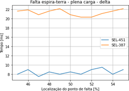
Source: The authors (2023).
Fig. 13 Turn-to-ground fault in the delta winding at no load.
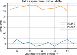
Source: The authors (2023).
Fig. 14 Turn-to-ground fault in the wye winding at full load.
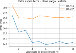
Source: The authors (2023).
Fig. 15 Turn-to-ground fault in the wye winding at no load.
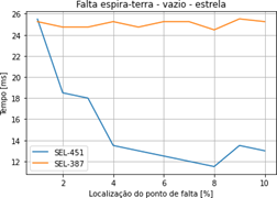
Source: The authors (2023).
- External faults
For external faults, neither the percentage differential of the SEL-
387 nor the alpha plane implemented in the SEL-451 operated, behaving as expected for the differential function.
- CONCLUSIONS
This article compared the alpha plane and the percentage differential applied to power transformer protection. Using differential protection through the alpha plane significantly reduced the time taken by the protection relay to detect the fault and issue the trip signal. With this shorter operating time, the electrical damage and mechanical stress on the faulted transformer are expected to decrease considerably.
Given the importance of the transformer in the electrical system and its high cost, this article showed that there are still possibilities to be explored in protecting this equipment.
Several lines of research can follow from this article:
- Tests with other internal fault models;
- Tests with a transformer model under
inrush conditions;
- Tests with a transformer model under overexcitation conditions;
- Tests with energization of transformers in parallel;
- Tests with the native alpha plane of a SEL device;
- Tests with oscillography from real cases;
- Tests with the alpha plane in
ACKNOWLEDGMENTS
The authors thank A1 Engenharia for its support.
REFERENCES
BLACKBURN, J.L., & DOMIN, T.J. Protective Relaying: Principles and Applications, Fourth Edition (4th ed.). CRC Press, 2014.
CHAPMAN, Stephen J. Fundamentos de Máquinas Elétricas.
Porto Alegre: Grupo A, 2013.
EPE. EPE-DEA-SEE-002/2022- NT-ONS DPL 0009/2022 –
CCEE 00285/2022 – NT Previsão de carga para o Planejamento Anual da Operação Energética 2022-2026. Available at: https://www.epe.gov.br/pt/publicacoes- dados-abertos/publicacoes/revisoes-quadrimestrais-da- carga. Accessed: May. 24, 2022.
- J. A. Ferrer and E. O. I. Schweitzer, Modern Solutions for Protection, Control, and Monitoring of Electrical Power Systems. Pullman, WA: Schweitzer Engineering Laboratories, Inc., 2010.
IEEE STD. C37.91 – 2021. IEEE Guide for Protecting Power Transformers. [s.l.] IEEE, 2021.
MAGRIN, Fabiano G. S. Novas Funções para a Proteção de Transformadores. Orientador: Profa. Dra. Maria Cristina Dias Tavares. 2017. 200 f. Tese (Doutorado em Engenharia Elétrica) – Universidade Estadual de Campinas, Campinas, 2017.
PAITHANKAR, Y.G. & BHIDE, S.R. Fundamentals of Power System Protection. New Delhi. Prentice-Hall of India, 2003.
RUSH, P. Proteção e automação de redes: conceito e aplicação. Peter Rush; coordenação da tradução José Antonio Jardini – São Paulo: Editora Blucher: Schneider, 2011.
SEL. Manual de Instrução SEL-311L: Line Current Differential Protection and Automation System. SEL, 2021. Available at: http://www.selinc.com. Accessed: Mar. 23, 2022.
SEL. Manual de Instrução SEL-387: Current Differential Overcurrent Relay. SEL, 2021. Available at: http://www.selinc.com. Accessed: Mar. 23, 2022.
SEL. Manual de Instrução SEL-451: Protection, Automation and Bay Control System. SEL, 2021. Available at: http://www.selinc.com. Accessed: Mar. 23, 2022.
SEL. Modern Line Current Differential Protection Solutions. SEL, 2014. Available at: http://www.selinc.com. Accessed: Nov. 15, 2022.
SEL. Proteção dos Transformadores Elevadores. SEL, 2019. Available at: http://www.selinc.com. Accessed: Oct. 09, 2022.
SEL. The Trajectories of Line Current Differential Faults in the Alpha Plane. SEL, 2014. Available at: http://www.selinc.com. Accessed: Nov. 15, 2022.
SEN, P.C. Principles of electric machines and power electronics, Third Edition (3rd ed.). WILEY, 2013. p. 40- 92.
WARRINGTON, A.R VAN C. Protective relays: their theory and practice. Vol. 1. Chapman & Hall, 1968.